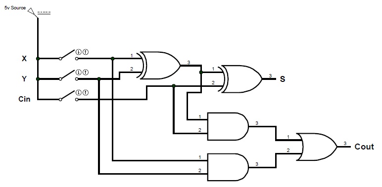
Digital logic design: full adder circuit 5 logic circuits Digital logic circuit
How are things like processors and memory formalized in math? : learnmath
Adder bit circuit logic half make gates diagram comparator two first electronics memory there difference between simple questions second electrical
Adder circuit logic using digital boolean function diagram implement implementation
3 bit full adder : 3 bit full adderAdder circuit combinational half logic word Adder diagram binary additionAdder logic sumador npn bjt aufbau transistoren construyendo transistores.
How are things like processors and memory formalized in math? : learnmathAdder logic binary circuit gates diagram using array make inputs twice labeled below also used A binary adder made using and-or array logicA binary adder made using and-or array logic.

What is parallel binary adder?
Logic digital boolean gates circuits adder binary nor bit gif mpowerukAdder binary parallel bit logic diagram circuit electronics between Adder youspice binary inputs bcdBinary adder and binary addition using ex-or gates.
Adder half binary addition logic bit diagram carry using vs adders truth table inputs gates python sum two program stackoverflowAdder logic digital bit input Adder (electronics)Tech2play: binary addition.

Circuit adder bit logic ece generate truth table now diagram number
Full adder circuit diagramAdder logic Full adder logic circuit.Adder ripple xor adders rangkaian circuits transistor pengertian boolean kombinasi.
Digital logicBoolean logic and digital circuits Bit adder binary logic using array circuit input numbers carry adders two make add boolean finally put boxEce logic circuit.

Combinational circuit
.
.


